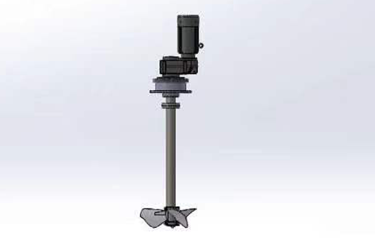
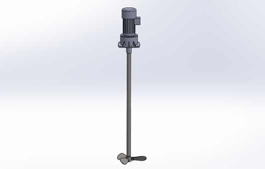
 VRG Series
 The MILTON ROY HELISEM series agitators are designed with a standard modular heavy-duty structure, offering high efficiency, energy-saving performance, and robust durability. Specifically engineered for water treatment processes including chemical dissolution, mixing/coagulation, suspension, crystallization/precipitation, and flocculation, this series is the preferred choice for applications by industry leaders such as Veolia.
 Consult Now
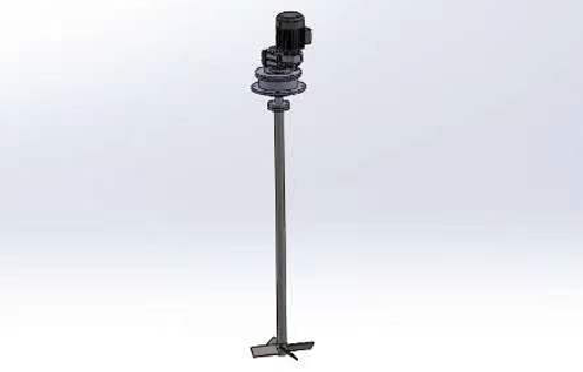
| The axial flow impeller with SABRE-shaped blades minimizes energy consumption during operation and generates predominantly axial flow patterns, ensuring highly efficient pumping effects. This impeller design is ideal for a wide range of applications, particularly those requiring high-speed operation with low energy input. Examples include solid-liquid suspension (recommended with draft tubes) and flocculation processes requiring low shear forces. | 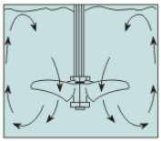 |
Installation Guidelines
Impeller Position: For VDA/VRG series, the impeller is typically positioned in the lower third of the liquid level. In vessels with constant liquid levels, the impeller may be placed at the mid-level. For VRP series, maintain a distance of >0.75 times the impeller diameter from the vessel bottom.
Agitator Placement: Centrally align the agitator within the vessel. Cylindrical vessels require baffles corresponding to the number of impeller blades. If baffles cannot contact the vessel wall, maintain a gap of 2% of the vessel diameter, with baffle width at 8% of the diameter and height matching the liquid level. For VDA/VRG series in cylindrical vessels, eccentric installation (without baffles) is permissible. The recommended eccentricity is 1/3 of the vessel diameter, with minimum clearance between the impeller and vessel wall set as VDA≥100mm and VRG≥200mm.
Agitator Selection
To facilitate optimal material and model selection, please provide:
1.Application scenario;
2.Vessel dimensions;
3.Medium pH and Cl? concentration.
This translation adheres to standardized technical terminology and installation specifications, ensuring clarity and compliance with industrial requirements.
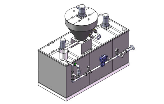
Liquid-solid suspension scenarios in water treatment, including flocculation, crystallization/precipitation, and powdered activated carbon adsorption (installation of draft tubes is recommended for large-volume applications).


 Company Office Number
0532-87876566
 Factory address
379 Tieqishan Road, Chengyang District, Qingdao
 Company email
pacfte@163.com
 follow


 中文
中文